Periodicity
Netgen is able to create periodic meshes, with them NGSolve can create periodic finite element spaces by mapping the degrees of freedom on the slave boundary to the ones on the master boundary. To use this functionality create a periodic mesh first:
Periodic Meshes
3D
If a geometry object has a periodic identification, Netgen creates a periodic mesh for the specified surfaces. In 3 dimensions, this identification is created using CSGeometry.PeriodicSurfaces(master,slave). Here we define a cube with periodicity in x-direction and create a periodic NGSolve mesh for it:
from netgen.csg import *

geo = CSGeometry()
left = Plane(Pnt(0,0,0),Vec(-1,0,0))
right = Plane(Pnt(1,0,0),Vec(1,0,0))
brick = OrthoBrick(Pnt(-1,0,0),Pnt(2,1,1)).bc("outer")
cube = brick * left * right
geo.Add(cube)
geo.PeriodicSurfaces(left,right)

from ngsolve import *
mesh = Mesh(geo.GenerateMesh(maxh=0.3))
2D
In two dimensions you can create periodic geometries with the copy parameter of the SplineGeometry.Append method. This defines the appended spline as the slave of the one given in copy:
Caution
The slave boundaries must be defined in the same direction as the master ones!
from netgen.geom2d import *

periodic = SplineGeometry()
pnts = [ (0,0), (1,0), (1,1), (0,1) ]
pnums = [periodic.AppendPoint(*p) for p in pnts]

periodic.Append ( ["line", pnums[0], pnums[1]],bc="outer")
# This should be our master edge so we need to save its number.
lright = periodic.Append ( ["line", pnums[1], pnums[2]], bc="periodic")
periodic.Append ( ["line", pnums[2], pnums[3]], bc="outer")
# Slave boundaries must be defined in the same direction as master ones,
# this is why the the point numbers of this spline are defined in the reverse direction,
# leftdomain and rightdomain must therefore be switched as well!
# We use the master number as the copy argument to create a slave edge.
periodic.Append ( ["line", pnums[0], pnums[3]], leftdomain=0, rightdomain=1, copy=lright, bc="periodic")

from ngsolve import *
mesh = Mesh(periodic.GenerateMesh(maxh=0.2))
1D
In one dimension you can add periodic identifications to points (This is not necessary for mesh creation of course, but lets NGSolve find the periodic vertices the same way as it finds the ones in higher dimensions). The added point numbers must be the ones returned from mesh.Add(MeshPoint). This is a manually created mesh with periodic boundaries:
from netgen.meshing import *

mesh = Mesh(dim=1)
pids = []
n = 50
for i in range(n+1):
    pids.append (mesh.Add (MeshPoint(Pnt(i/n, 0, 0))))
for i in range(n):
    mesh.Add(Element1D([pids[i],pids[i+1]],index=1))
mesh.Add (Element0D( pids[0], index=1))
mesh.Add (Element0D( pids[n], index=2))
mesh.AddPointIdentification(pids[0],pids[n],1,2)
Periodic FESpace
The periodic finite element space is created using the generator function Periodic. A quasi-periodic space can be created the same way if the optional parameter ‘phase’ is set.
Caution
The phase shifts must be given in the same order as the definition of the periodic boundaries in the geometry!
We can solve a periodic problem using the above defined mesh:
fes = Periodic(H1(mesh,order=3,dirichlet="outer"))
u,v = fes.TrialFunction(), fes.TestFunction()
a = BilinearForm(fes,symmetric=True)
a += SymbolicBFI(grad(u) * grad(v))
f = LinearForm(fes)
f += SymbolicLFI(x*v)
u = GridFunction(fes,"u")
with TaskManager():
a.Assemble()
f.Assemble()
u.vec.data = a.mat.Inverse(fes.FreeDofs()) * f.vec
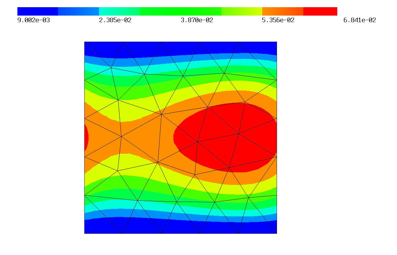
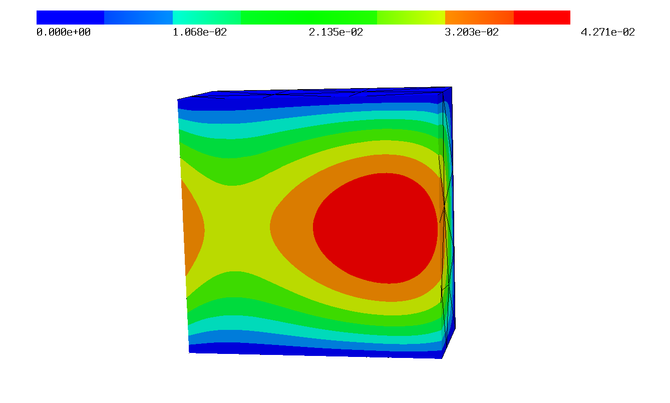
Draw(u)
The solution of this problem plotted in 2D and in 3D: